We have seen in one of our previous articles how utilizing specific filtering methods better provides technicians with a more efficient search process to view configuration commands on our routing and switching devices. Refer to (cisco show running-configuration filter) .
While at first it may or may not appear to be such a necessary endeavor at any one particular time, however, if you find yourself constantly in need of opening a console session, it would be most beneficial to develop a smart habit by enforcing these time saving methods.
For example if you’re constantly using the show run command, it may not dawn on you that the amount of time you spend waiting for the routing or switch device to go through the thinking process can add up exponentially. You may find that by the end of the week you spent over an hour or more wasted in watching and scrolling. It reminds me of an old tune by the Moody Blues entitled, “Watching and Waiting” If its not the actual name of the song I assure you that those are the first lines in the song lyrics. J
Being part of a training group in which you coach where one is constantly in an environment surrounded by students and other IT professionals working towards validating their skill sets, its imperative to utilize such time saving approaches. Not to mention that what you demonstrate can positively rub off on to others.
Just to further extrapolate; An IT training facilitator delegated with the chore in need of scrolling through basic configurations from top to bottom, will find the following command, ‘show run exclude !’ , plays a useful role in reducing the time it takes when bypassing all of those seemingly incessant exclamation points, not to mention the time saving benefits when you copy the configuration to a notepad which further complements your time savings when the need arises to add those same configurations on other router or switch devices in your lab or other non productive testing environments.
I know what you may be thinking by now. Your thinking…, “but I like having the exclamation points and besides they are needed because it is important for documenting comments and it assists me in queuing where one configuration ends and where one configuration begins.” No argument here. You’re right. My reasoning for using this sample line command was to emphasize the good habits you are instilling. It is apparently more useful and beneficial using show run begin or show run include as depicted in the article previously referenced, since it sends you to the specific area of the configuration depending on the object you would want to search. Again, an excellent time savings endeavor.
More time saving techniques can be adhered to by practicing the “ do” command which can allow you to apply show commands normally only viewed from the execution mode but instead used in the global configuration terminal mode. Example While in the ( config )# ”Do show ip int brief” (Notice I didn’t say do show run) but you can.
Where is the times savings here for that endeavor? It gives you one less level to scale down to, and one less level to move you back up. Add that up in a days work. J
Let’s take a look at some other fun ‘saving tip’ navigational skills you can do on your switches without using the show run command.
Here is what I will go over: Show vlan-s
Show int tr
Sh eth summ
Let’s say you want to check on the specific trunks that you have configured: Instead of ‘show run’, you can do ‘sh vlans-s’.
You can then view the port numbers that are shown as vlans. If you don’t see a port number then you know the ports that are missing are configured as trunk ports.
On the other hand, you can do a ‘sh int tr’: short for show interface trunk; this will provide you a view of which ports are set up as trunk ports.
The command ‘sh eth summ’: short for show ether-channel summary. This would provide us with the ports configured as Ether channel groups, assuming they were configured. If nothing shows up, that means none have been configured.
Ether Channel is used to provide for load balancing and fault tolerance, but that is for another topic at another time, and is beyond the scope of this article.
These are only just a few command lines to help us become more aware of time saving skills that we would otherwise unknowingly drain away in our daily schedule.
By enforcing smart and skillful navigational habits, we will be keeping our minds sharp and our actions more efficient in many endeavors we undertake.
Keep on practicing.
Tuesday, February 23, 2010


Monday, July 20, 2009
GRE over IPSec with EIGRP to Route Through Two Remote Sites Configuration Example
Introduction
Let's consider the scenario when our company has two sites. They are equally big and some users require accessing other network devices directly by using its local IPs, or maybe you even have to replicate domain controllers over this tunnel. Let's say you want to access OWA and not too often check some shared files. The reason why I said not too often is because this will create some serious traffic over internet, if file is big.
Cisco GRE-Based VPN is the best choice for use, because it supports routing, QoS, Multicast and also non-IP protocols. You can configure it using SDM or CLI. The main downside is that this configuration is not multivendor. So both routers has to be Cisco routers with IOS that support VPN.
Refer here for differences between VPNs:
http://www.cisco.com/en/US/prod/collateral/iosswrel/ps6537/ps6586/ps6635/ps7180/prod_brochure0900aecd80582078.pdf
Network Diagram
Please check the diagram before you start to read further.

Components Used
- 2 Cisco routers 3745 running Cisco IOS (C3745-ADVIPSERVICESK9-M), Version 12.4(9)T1
- 2 Windows XP
- 1 Windows Server 2003 Enterprise
Configuration
This process has 3 steps:
- Configure the Generic Routing Encapsulation (GRE) Tunnels
- Configure Encryption for the GRE Tunnels
- Configure the Routing Protocol
Configure the GRE Tunnels
R1:
interface Tunnel0
ip address 172.31.0.1 255.255.0.0
tunnel source FastEthernet0/1
tunnel destination 172.16.0.2
R2:
interface Tunnel0
ip address 172.31.0.2 255.255.0.0
tunnel source FastEthernet0/1
tunnel destination 172.16.0.1
Check if you can ping by interface IP and by Tunnel IPs.
R2#ping 172.31.0.1
Type escape sequence to abort.
Sending 5, 100-byte ICMP Echos to 172.31.0.1, timeout is 2 seconds:
!!!!!
Success rate is 100 percent (5/5), round-trip min/avg/max = 12/12/12 ms
R2#ping 172.16.0.1
Type escape sequence to abort.
Sending 5, 100-byte ICMP Echos to 172.16.0.1, timeout is 2 seconds:
!!!!!
Success rate is 100 percent (5/5), round-trip min/avg/max = 8/16/48 ms
R1#ping 172.16.0.1
Type escape sequence to abort.
Sending 5, 100-byte ICMP Echos to 172.16.0.1, timeout is 2 seconds:
!!!!!
Success rate is 100 percent (5/5), round-trip min/avg/max = 1/1/4 ms
R1#ping 172.31.0.1
Type escape sequence to abort.
Sending 5, 100-byte ICMP Echos to 172.31.0.1, timeout is 2 seconds:
!!!!!
Success rate is 100 percent (5/5), round-trip min/avg/max = 1/1/4 ms
Configure the Encryption for the GRE Tunnels
First create a access list to define which traffic to encypt:
R1:
access-list 100 permit gre host 172.16.0.1 host 172.16.0.2
R2:
access-list 100 permit gre host 172.16.0.2 host 172.16.0.1
Configure an Internet Security Association and Key Management Protocol (ISAKMP) policy, an ISAKMP key, and an IPSec transform set. The ISAKMP policy, key, and IPSec transform set must match on both sides of a single tunnel.
R1 & R2:
crypto isakmp policy 1
authentication pre-share
crypto isakmp key cisco123 address 0.0.0.0 0.0.0.0
!
!
crypto ipsec transform-set strong esp-3des esp-md5-hmac
mode transport
Configure the crypto map
R1:
crypto map vpn 10 ipsec-isakmp
set peer 172.16.0.2
set transform-set strong
match address 100
R2:
crypto map vpn 10 ipsec-isakmp
set peer 172.16.0.1
set transform-set strong
match address 100
Apply on BOTH:
R1 & R2:
interface FastEthernet0/1
crypto map vpn
interface Tunnel0
crypto map vpn
Enable EIGRP
R1:
router eigrp 60
network 172.31.0.0
network 192.168.0.0 0.0.255.255
auto-summary
no eigrp log-neighbor-changes
R2:
router eigrp 60
network 10.0.0.0
network 172.31.0.0
auto-summary
no eigrp log-neighbor-changes
Full config
R1:
!
version 12.4
service timestamps debug datetime msec
service timestamps log datetime msec
no service password-encryption
!
hostname R1
!
boot-start-marker
boot-end-marker
!
logging buffered 51200 warnings
enable secret 5 $1$JZ2K$15BvDKP555bzNmcnoxc2D.
!
!
aaa session-id common
!
resource policy
!
memory-size iomem 5
ip cef
!
!
username cisc0 privilege 15 password 0 cisc0
!
!
!
crypto isakmp policy 1
authentication pre-share
crypto isakmp key cisco123 address 0.0.0.0 0.0.0.0
!
!
crypto ipsec transform-set strong esp-3des esp-md5-hmac
mode transport
!
crypto map vpn 10 ipsec-isakmp
set peer 172.16.0.2
set transform-set strong
match address 100
!
!
!
!
!
interface Tunnel0
ip address 172.31.0.1 255.255.0.0
tunnel source FastEthernet0/1
tunnel destination 172.16.0.2
crypto map vpn
!
interface FastEthernet0/0
ip address 192.168.0.1 255.255.255.0
ip nat inside
ip virtual-reassembly
duplex auto
speed auto
!
interface FastEthernet0/1
ip address 172.16.0.1 255.255.0.0
ip nat outside
ip virtual-reassembly
duplex auto
speed auto
crypto map vpn
!
router eigrp 60
network 172.31.0.0
network 192.168.0.0 0.0.255.255
auto-summary
no eigrp log-neighbor-changes
!
!
!
access-list 100 permit gre host 172.16.0.1 host 172.16.0.2
!
!
!
!
!
!
control-plane
!
!
!
!
!
!
!
!
!
!
alias exec s show ip inter brief
alias exec sr show run
!
line con 0
exec-timeout 0 0
logging synchronous
line aux 0
line vty 0 4
password v
transport input telnet ssh
!
!
!
!
end
R2:
Building configuration...
Current configuration : 1412 bytes
!
version 12.4
service timestamps debug datetime msec
service timestamps log datetime msec
no service password-encryption
!
hostname R2
!
boot-start-marker
boot-end-marker
!
enable secret 5 $1$aIoH$XR1H76kiRYuPGtAV07ST3.
!
no aaa new-model
!
resource policy
!
memory-size iomem 5
ip cef
!
!
!
!
!
!
!
!
!
!
!
!
!
!
!
!
!
!
!
!
!
!
!
!
!
!
crypto isakmp policy 1
authentication pre-share
crypto isakmp key cisco123 address 0.0.0.0 0.0.0.0
!
!
crypto ipsec transform-set strong esp-3des esp-md5-hmac
mode transport
!
crypto map vpn 10 ipsec-isakmp
set peer 172.16.0.1
set transform-set strong
match address 100
!
!
!
!
!
interface Tunnel0
ip address 172.31.0.2 255.255.0.0
tunnel source FastEthernet0/1
tunnel destination 172.16.0.1
crypto map vpn
!
interface FastEthernet0/0
ip address 10.0.0.2 255.0.0.0
ip nat inside
ip virtual-reassembly
duplex auto
speed auto
!
interface FastEthernet0/1
ip address 172.16.0.2 255.255.0.0
ip nat outside
ip virtual-reassembly
duplex auto
speed auto
crypto map vpn
!
router eigrp 60
network 10.0.0.0
network 172.31.0.0
auto-summary
no eigrp log-neighbor-changes
!
!
!
ip http server
no ip http secure-server
ip nat inside source list 10 interface FastEthernet0/1 overload
!
access-list 100 permit gre host 172.16.0.2 host 172.16.0.1
!
!
!
!
!
!
control-plane
!
!
!
!
!
!
!
!
!
!
alias exec s show ip inter brief
!
line con 0
line aux 0
line vty 0 4
login
!
!
end
This post is based on:
GRE over IPSec with EIGRP to Route Through a Hub and Multiple Remote Sites Configuration
Other Examples:
http://www.cisco.com/en/US/tech/tk583/tk372/technologies_configuration_example09186a008009438e.shtml
Let's consider the scenario when our company has two sites. They are equally big and some users require accessing other network devices directly by using its local IPs, or maybe you even have to replicate domain controllers over this tunnel. Let's say you want to access OWA and not too often check some shared files. The reason why I said not too often is because this will create some serious traffic over internet, if file is big.
Cisco GRE-Based VPN is the best choice for use, because it supports routing, QoS, Multicast and also non-IP protocols. You can configure it using SDM or CLI. The main downside is that this configuration is not multivendor. So both routers has to be Cisco routers with IOS that support VPN.
Refer here for differences between VPNs:
http://www.cisco.com/en/US/prod/collateral/iosswrel/ps6537/ps6586/ps6635/ps7180/prod_brochure0900aecd80582078.pdf
Network Diagram
Please check the diagram before you start to read further.

Components Used
- 2 Cisco routers 3745 running Cisco IOS (C3745-ADVIPSERVICESK9-M), Version 12.4(9)T1
- 2 Windows XP
- 1 Windows Server 2003 Enterprise
Configuration
This process has 3 steps:
- Configure the Generic Routing Encapsulation (GRE) Tunnels
- Configure Encryption for the GRE Tunnels
- Configure the Routing Protocol
Configure the GRE Tunnels
R1:
interface Tunnel0
ip address 172.31.0.1 255.255.0.0
tunnel source FastEthernet0/1
tunnel destination 172.16.0.2
R2:
interface Tunnel0
ip address 172.31.0.2 255.255.0.0
tunnel source FastEthernet0/1
tunnel destination 172.16.0.1
Check if you can ping by interface IP and by Tunnel IPs.
R2#ping 172.31.0.1
Type escape sequence to abort.
Sending 5, 100-byte ICMP Echos to 172.31.0.1, timeout is 2 seconds:
!!!!!
Success rate is 100 percent (5/5), round-trip min/avg/max = 12/12/12 ms
R2#ping 172.16.0.1
Type escape sequence to abort.
Sending 5, 100-byte ICMP Echos to 172.16.0.1, timeout is 2 seconds:
!!!!!
Success rate is 100 percent (5/5), round-trip min/avg/max = 8/16/48 ms
R1#ping 172.16.0.1
Type escape sequence to abort.
Sending 5, 100-byte ICMP Echos to 172.16.0.1, timeout is 2 seconds:
!!!!!
Success rate is 100 percent (5/5), round-trip min/avg/max = 1/1/4 ms
R1#ping 172.31.0.1
Type escape sequence to abort.
Sending 5, 100-byte ICMP Echos to 172.31.0.1, timeout is 2 seconds:
!!!!!
Success rate is 100 percent (5/5), round-trip min/avg/max = 1/1/4 ms
Configure the Encryption for the GRE Tunnels
First create a access list to define which traffic to encypt:
R1:
access-list 100 permit gre host 172.16.0.1 host 172.16.0.2
R2:
access-list 100 permit gre host 172.16.0.2 host 172.16.0.1
Configure an Internet Security Association and Key Management Protocol (ISAKMP) policy, an ISAKMP key, and an IPSec transform set. The ISAKMP policy, key, and IPSec transform set must match on both sides of a single tunnel.
R1 & R2:
crypto isakmp policy 1
authentication pre-share
crypto isakmp key cisco123 address 0.0.0.0 0.0.0.0
!
!
crypto ipsec transform-set strong esp-3des esp-md5-hmac
mode transport
Configure the crypto map
R1:
crypto map vpn 10 ipsec-isakmp
set peer 172.16.0.2
set transform-set strong
match address 100
R2:
crypto map vpn 10 ipsec-isakmp
set peer 172.16.0.1
set transform-set strong
match address 100
Apply on BOTH:
R1 & R2:
interface FastEthernet0/1
crypto map vpn
interface Tunnel0
crypto map vpn
Enable EIGRP
R1:
router eigrp 60
network 172.31.0.0
network 192.168.0.0 0.0.255.255
auto-summary
no eigrp log-neighbor-changes
R2:
router eigrp 60
network 10.0.0.0
network 172.31.0.0
auto-summary
no eigrp log-neighbor-changes
Full config
R1:
!
version 12.4
service timestamps debug datetime msec
service timestamps log datetime msec
no service password-encryption
!
hostname R1
!
boot-start-marker
boot-end-marker
!
logging buffered 51200 warnings
enable secret 5 $1$JZ2K$15BvDKP555bzNmcnoxc2D.
!
!
aaa session-id common
!
resource policy
!
memory-size iomem 5
ip cef
!
!
username cisc0 privilege 15 password 0 cisc0
!
!
!
crypto isakmp policy 1
authentication pre-share
crypto isakmp key cisco123 address 0.0.0.0 0.0.0.0
!
!
crypto ipsec transform-set strong esp-3des esp-md5-hmac
mode transport
!
crypto map vpn 10 ipsec-isakmp
set peer 172.16.0.2
set transform-set strong
match address 100
!
!
!
!
!
interface Tunnel0
ip address 172.31.0.1 255.255.0.0
tunnel source FastEthernet0/1
tunnel destination 172.16.0.2
crypto map vpn
!
interface FastEthernet0/0
ip address 192.168.0.1 255.255.255.0
ip nat inside
ip virtual-reassembly
duplex auto
speed auto
!
interface FastEthernet0/1
ip address 172.16.0.1 255.255.0.0
ip nat outside
ip virtual-reassembly
duplex auto
speed auto
crypto map vpn
!
router eigrp 60
network 172.31.0.0
network 192.168.0.0 0.0.255.255
auto-summary
no eigrp log-neighbor-changes
!
!
!
access-list 100 permit gre host 172.16.0.1 host 172.16.0.2
!
!
!
!
!
!
control-plane
!
!
!
!
!
!
!
!
!
!
alias exec s show ip inter brief
alias exec sr show run
!
line con 0
exec-timeout 0 0
logging synchronous
line aux 0
line vty 0 4
password v
transport input telnet ssh
!
!
!
!
end
R2:
Building configuration...
Current configuration : 1412 bytes
!
version 12.4
service timestamps debug datetime msec
service timestamps log datetime msec
no service password-encryption
!
hostname R2
!
boot-start-marker
boot-end-marker
!
enable secret 5 $1$aIoH$XR1H76kiRYuPGtAV07ST3.
!
no aaa new-model
!
resource policy
!
memory-size iomem 5
ip cef
!
!
!
!
!
!
!
!
!
!
!
!
!
!
!
!
!
!
!
!
!
!
!
!
!
!
crypto isakmp policy 1
authentication pre-share
crypto isakmp key cisco123 address 0.0.0.0 0.0.0.0
!
!
crypto ipsec transform-set strong esp-3des esp-md5-hmac
mode transport
!
crypto map vpn 10 ipsec-isakmp
set peer 172.16.0.1
set transform-set strong
match address 100
!
!
!
!
!
interface Tunnel0
ip address 172.31.0.2 255.255.0.0
tunnel source FastEthernet0/1
tunnel destination 172.16.0.1
crypto map vpn
!
interface FastEthernet0/0
ip address 10.0.0.2 255.0.0.0
ip nat inside
ip virtual-reassembly
duplex auto
speed auto
!
interface FastEthernet0/1
ip address 172.16.0.2 255.255.0.0
ip nat outside
ip virtual-reassembly
duplex auto
speed auto
crypto map vpn
!
router eigrp 60
network 10.0.0.0
network 172.31.0.0
auto-summary
no eigrp log-neighbor-changes
!
!
!
ip http server
no ip http secure-server
ip nat inside source list 10 interface FastEthernet0/1 overload
!
access-list 100 permit gre host 172.16.0.2 host 172.16.0.1
!
!
!
!
!
!
control-plane
!
!
!
!
!
!
!
!
!
!
alias exec s show ip inter brief
!
line con 0
line aux 0
line vty 0 4
login
!
!
end
This post is based on:
GRE over IPSec with EIGRP to Route Through a Hub and Multiple Remote Sites Configuration
Other Examples:
http://www.cisco.com/en/US/tech/tk583/tk372/technologies_configuration_example09186a008009438e.shtml
Monday, July 13, 2009
Teleworker: Thin-Client SSL VPN (WebVPN) IOS Configuration Example with SDM
Before we proceed to the hard core part let's take a look at Cisco promotion video first, Cisco Teleworking Solutions - The World Is Your Office:
One of the key portion of that advanced product is SSL VPN. It used to be called in the past Web VPN. It is usefull in the situations where you need to reach network resources in your company LAN from remote location. Most likely it will be home, cofee shop etc. In this post we will focus on how to access your computer at work from home using Remote Desktop, OWA (Outlook Web Access) and internal website with News and Anouncements, it can be even Sharepoint site.
Take a look at the logical diagram:
One of the key portion of that advanced product is SSL VPN. It used to be called in the past Web VPN. It is usefull in the situations where you need to reach network resources in your company LAN from remote location. Most likely it will be home, cofee shop etc. In this post we will focus on how to access your computer at work from home using Remote Desktop, OWA (Outlook Web Access) and internal website with News and Anouncements, it can be even Sharepoint site.
Take a look at the logical diagram:

As you can see we have 2 Routers. One of them for your remote location (R2) and one of them (R1) at our company site. R2 does not have to be cisco router, it just has to provide internet connection. The network between R1 and R2 (172.16.0.0/16) acts as an internet in this lab environment. In this lab both routers are Cisco 3745 with IOS C3745-ADVIPSERVICESK9-M 12.4 (9) T1.
The configuration can be done via SDM (GUI software to configure Cisco Devices) or CLI.
R2 config:
R2#show run
Building configuration...
Current configuration : 935 bytes
!
version 12.4
service timestamps debug datetime msec
service timestamps log datetime msec
no service password-encryption
!
hostname R2
!
boot-start-marker
boot-end-marker
!
enable secret s
!
no aaa new-model
!
resource policy
!
memory-size iomem 5
ip cef
!
interface FastEthernet0/0
ip address 10.0.0.2 255.0.0.0
ip nat inside
ip virtual-reassembly
duplex auto
speed auto
!
interface FastEthernet0/1
ip address 172.16.0.2 255.255.0.0
ip nat outside
ip virtual-reassembly
duplex auto
speed auto
!
!
!
ip http server
no ip http secure-server
ip nat inside source list 10 interface FastEthernet0/1 overload
!
access-list 10 permit 10.0.0.0 0.255.255.255
!
control-plane
!
alias exec s show ip inter brief
!
line con 0
exec-timeout 0 0
logging synchronous
line aux 0
line vty 0 4
password v
login
!
!
end
Below is a R1 config:
Current configuration : 3841 bytes
!
version 12.4
service timestamps debug datetime msec
service timestamps log datetime msec
no service password-encryption
!
hostname R1
!
boot-start-marker
boot-end-marker
!
logging buffered 51200 warnings
enable secret s
!
aaa new-model
!
!
aaa authentication login default local
aaa authentication login sdm_vpn_xauth_ml_1 local
aaa authorization exec default local
!
aaa session-id common
!
resource policy
!
memory-size iomem 5
ip cef
!
!
crypto pki trustpoint TP-self-signed-998521732
enrollment selfsigned
subject-name cn=IOS-Self-Signed-Certificate-998521732
revocation-check none
rsakeypair TP-self-signed-998521732
!
!
crypto pki certificate chain TP-self-signed-998521732
certificate self-signed 01
!---- output cut ---
ED20B032 D4BDEF14 5A114136 4C9F1794 3C3AA01E E670BC18 FC19B9B5
quit
username cisc0 privilege 15 password 0 cisc0
!
!
!
!
!
!
!
interface FastEthernet0/0
ip address 192.168.0.1 255.255.255.0
ip nat inside
ip virtual-reassembly
duplex auto
speed auto
!
interface FastEthernet0/1
ip address 172.16.0.1 255.255.0.0
ip nat outside
ip virtual-reassembly
duplex auto
speed auto
!
!
!
ip http server
ip http authentication local
ip http secure-server
ip nat inside source list 10 interface FastEthernet0/1 overload
!
access-list 10 permit 192.168.0.0 0.0.0.255
!
!
!
!
!
!
control-plane
!
!
!
!
!
!
!
!
!
!
alias exec s show ip inter brief
!
line con 0
exec-timeout 0 0
logging synchronous
line aux 0
line vty 0 4
password v
transport input telnet ssh
!
!
webvpn gateway gateway_1
ip address 172.16.0.1 port 443
http-redirect port 80
ssl trustpoint TP-self-signed-998521732
inservice
!
webvpn context First
title-color #FFFF00
secondary-color white
text-color black
ssl authenticate verify all
!
url-list "First"
heading "Web Sites"
url-text "OWA" url-value "http://192.168.0.10/owa/exchange"
url-text "News" url-value "http://192.168.0.10/news"
!
port-forward "portforward_list_1"
local-port 3000 remote-server "192.168.0.100" remote-port 3389 description "XP1 RD"
local-port 3001 remote-server "192.168.0.10" remote-port description "DC1 Remote Desktop"
!
policy group policy_1
url-list "First"
port-forward "portforward_list_1"
default-group-policy policy_1
aaa authentication list sdm_vpn_xauth_ml_1
gateway gateway_1 domain mydomain
inservice
!
!
end
If you accomplish that config on the XP2 you can connect using web browser. After you login you need to Start Application access. The Java applet will create a VPN and using IP 127.0.0.1:3000 you will be able to connect to your computer at work while being at home!
Login screen from XP2:

After you login and click Start Application Access you will see:
More info:
http://www.cisco.com/en/US/products/ps6496/products_configuration_example09186a008072aa61.shtml
http://www.cisco.com/en/US/products/ps6496/products_configuration_example09186a008071c58b.shtml
![Reblog this post [with Zemanta]](https://lh3.googleusercontent.com/blogger_img_proxy/AEn0k_v6PvoC43fbxbskuMxKAwNyjgs0EKeYB9bWTkdXM_GyqtrYJ7JUpbRWhzAiPA5QKEmjfusfyHQaGzcn2uwfmbJNO8c1tCKgOzn0LNyE6INFds1wUfEA3NB39sPgQKc_FcDwKQIBYAjZWkcWhiURSypa=s0-d)
Thursday, July 9, 2009
cisco show running-configuration filter
Tired of having to scroll through your whole running-configuration just to read one line at the very end? Cisco has an in built command filter that allows you to specify more accurately what information you want from the running configurations, and mastering these commands not only makes you look like you know what you are doing ,they could save you lots of time and frustration having to look through irrelevant information.
There are mainly three widely used filter in the running config. BEGIN, EXCLUDE and INCLUDE. We can see this issuing the show running-configuration (sh run since we're trying to save time here) followed by the vertical bar key (|). We hit the question mark to see our options.
R1#sh run | ?
append Append redirected output to URL (URLs supporting append operation
only)
begin Begin with the line that matches
exclude Exclude lines that match
include Include lines that match
redirect Redirect output to URL
section Filter a section of output
tee Copy output to URL
The begin command filters through the configuration until it hits the first line that matches whatever word you put in after. Having an understanding of how lines are expressed in the configuration comes in handy when choosing what to type in.
As an example, here is the running-configuration of a router I am currently working on
R1#sh run
Building configuration...
Current configuration : 1238 bytes
!
version 12.4
service timestamps debug datetime msec
service timestamps log datetime msec
no service password-encryption
!
hostname R1
!
boot-start-marker
boot-end-marker
!
!
no aaa new-model
!
resource policy
!
memory-size iomem 5
!
!
ip cef
no ip domain lookup
!
!
!
username R2 password 0 lanwan
!
!
!
interface Serial0/0
no ip address
encapsulation frame-relay
serial restart-delay 0
no dce-terminal-timing-enable
no frame-relay inverse-arp
frame-relay lmi-type ansi
!
interface Serial0/0.2 point-to-point
ip address 10.0.12.1 255.255.255.0
no cdp enable
frame-relay interface-dlci 102
!
interface Serial0/1
ip address 10.1.12.1 255.255.255.0
encapsulation ppp
serial restart-delay 0
no dce-terminal-timing-enable
ppp authentication chap
!
interface Serial0/2
no ip address
shutdown
serial restart-delay 0
no dce-terminal-timing-enable
!
interface Serial0/3
no ip address
shutdown
serial restart-delay 0
no dce-terminal-timing-enable
!
interface FastEthernet1/0
ip address 172.16.1.1 255.255.255.0
duplex auto
speed auto
!
ip http server
!
ip route 192.168.2.0 255.255.255.0 Serial0/0.2
!
!
no cdp run
!
control-plane
!
!
line con 0
exec-timeout 0 0
logging synchronous
line aux 0
line vty 0 4
!
!
end
If we only wanted informatin on the configured static routes, using the begin command we can filter to the exact line.
R1#sh run | begin ip route
ip route 192.168.2.0 255.255.255.0 Serial0/0.2
!
!
no cdp run
!
control-plane
!
!
line con 0
exec-timeout 0 0
logging synchronous
line aux 0
line vty 0 4
!
!
end
and we see that this begins the display with the first line that has the words "ip route"
We can use the include command to only display lines that have the words "ip route"
R1#sh run | include ip route
ip route 192.168.2.0 255.255.255.0 Serial0/0.2
This is much more succint output and gives a much neater and pleasing to the eye display.
The Exclude command eliminates all the lines that have the word you put in. For example, if you wanted to remove all the lines that have the word "line".
R1#sh run | exclude line
Building configuration...
Current configuration : 1238 bytes
!
version 12.4
service timestamps debug datetime msec
service timestamps log datetime msec
no service password-encryption
!
hostname R1
!
boot-start-marker
boot-end-marker
!
!
no aaa new-model
!
resource policy
!
memory-size iomem 5
!
!
ip cef
no ip domain lookup
!
!
!
username R2 password 0 lanwan
!
!
!
interface Serial0/0
no ip address
encapsulation frame-relay
serial restart-delay 0
no dce-terminal-timing-enable
no frame-relay inverse-arp
frame-relay lmi-type ansi
!
interface Serial0/0.2 point-to-point
ip address 10.0.12.1 255.255.255.0
no cdp enable
frame-relay interface-dlci 102
!
interface Serial0/1
ip address 10.1.12.1 255.255.255.0
encapsulation ppp
serial restart-delay 0
no dce-terminal-timing-enable
ppp authentication chap
!
interface Serial0/2
no ip address
shutdown
serial restart-delay 0
no dce-terminal-timing-enable
!
interface Serial0/3
no ip address
shutdown
serial restart-delay 0
no dce-terminal-timing-enable
!
interface FastEthernet1/0
ip address 172.16.1.1 255.255.255.0
duplex auto
speed auto
!
ip http server
!
ip route 192.168.2.0 255.255.255.0 Serial0/0.2
!
!
no cdp run
!
control-plane
!
!
exec-timeout 0 0
logging synchronous
!
!
end
Personally , I prefer the BEGIN and INCLUDE commands as they are more effective. Further more the output of the EXCLUDE command leaves some information hanging and that may be a bit confusing.
There are mainly three widely used filter in the running config. BEGIN, EXCLUDE and INCLUDE. We can see this issuing the show running-configuration (sh run since we're trying to save time here) followed by the vertical bar key (|). We hit the question mark to see our options.
R1#sh run | ?
append Append redirected output to URL (URLs supporting append operation
only)
begin Begin with the line that matches
exclude Exclude lines that match
include Include lines that match
redirect Redirect output to URL
section Filter a section of output
tee Copy output to URL
The begin command filters through the configuration until it hits the first line that matches whatever word you put in after. Having an understanding of how lines are expressed in the configuration comes in handy when choosing what to type in.
As an example, here is the running-configuration of a router I am currently working on
R1#sh run
Building configuration...
Current configuration : 1238 bytes
!
version 12.4
service timestamps debug datetime msec
service timestamps log datetime msec
no service password-encryption
!
hostname R1
!
boot-start-marker
boot-end-marker
!
!
no aaa new-model
!
resource policy
!
memory-size iomem 5
!
!
ip cef
no ip domain lookup
!
!
!
username R2 password 0 lanwan
!
!
!
interface Serial0/0
no ip address
encapsulation frame-relay
serial restart-delay 0
no dce-terminal-timing-enable
no frame-relay inverse-arp
frame-relay lmi-type ansi
!
interface Serial0/0.2 point-to-point
ip address 10.0.12.1 255.255.255.0
no cdp enable
frame-relay interface-dlci 102
!
interface Serial0/1
ip address 10.1.12.1 255.255.255.0
encapsulation ppp
serial restart-delay 0
no dce-terminal-timing-enable
ppp authentication chap
!
interface Serial0/2
no ip address
shutdown
serial restart-delay 0
no dce-terminal-timing-enable
!
interface Serial0/3
no ip address
shutdown
serial restart-delay 0
no dce-terminal-timing-enable
!
interface FastEthernet1/0
ip address 172.16.1.1 255.255.255.0
duplex auto
speed auto
!
ip http server
!
ip route 192.168.2.0 255.255.255.0 Serial0/0.2
!
!
no cdp run
!
control-plane
!
!
line con 0
exec-timeout 0 0
logging synchronous
line aux 0
line vty 0 4
!
!
end
If we only wanted informatin on the configured static routes, using the begin command we can filter to the exact line.
R1#sh run | begin ip route
ip route 192.168.2.0 255.255.255.0 Serial0/0.2
!
!
no cdp run
!
control-plane
!
!
line con 0
exec-timeout 0 0
logging synchronous
line aux 0
line vty 0 4
!
!
end
and we see that this begins the display with the first line that has the words "ip route"
We can use the include command to only display lines that have the words "ip route"
R1#sh run | include ip route
ip route 192.168.2.0 255.255.255.0 Serial0/0.2
This is much more succint output and gives a much neater and pleasing to the eye display.
The Exclude command eliminates all the lines that have the word you put in. For example, if you wanted to remove all the lines that have the word "line".
R1#sh run | exclude line
Building configuration...
Current configuration : 1238 bytes
!
version 12.4
service timestamps debug datetime msec
service timestamps log datetime msec
no service password-encryption
!
hostname R1
!
boot-start-marker
boot-end-marker
!
!
no aaa new-model
!
resource policy
!
memory-size iomem 5
!
!
ip cef
no ip domain lookup
!
!
!
username R2 password 0 lanwan
!
!
!
interface Serial0/0
no ip address
encapsulation frame-relay
serial restart-delay 0
no dce-terminal-timing-enable
no frame-relay inverse-arp
frame-relay lmi-type ansi
!
interface Serial0/0.2 point-to-point
ip address 10.0.12.1 255.255.255.0
no cdp enable
frame-relay interface-dlci 102
!
interface Serial0/1
ip address 10.1.12.1 255.255.255.0
encapsulation ppp
serial restart-delay 0
no dce-terminal-timing-enable
ppp authentication chap
!
interface Serial0/2
no ip address
shutdown
serial restart-delay 0
no dce-terminal-timing-enable
!
interface Serial0/3
no ip address
shutdown
serial restart-delay 0
no dce-terminal-timing-enable
!
interface FastEthernet1/0
ip address 172.16.1.1 255.255.255.0
duplex auto
speed auto
!
ip http server
!
ip route 192.168.2.0 255.255.255.0 Serial0/0.2
!
!
no cdp run
!
control-plane
!
!
exec-timeout 0 0
logging synchronous
!
!
end
Personally , I prefer the BEGIN and INCLUDE commands as they are more effective. Further more the output of the EXCLUDE command leaves some information hanging and that may be a bit confusing.
Monday, June 29, 2009
configuring cisco catalyst switch VTP modes
VTP (Vlan Trunking Protocol) modes are different ways a switch can be set to share or interact with VTP advertisements. The three modes are Server, client and Transparent.
Server mode is the default setting for Cisco catalyst switches. Within any VTP domain, there must contain at least one switch configured in server mode. When in this mode, the switch can be used to add, modify or delete VLAN related infrormation. These changes are then advertised to other switches in the same domain that are configured as either servers or clients. The receiving switches then compare the revision number from the received update and if the revision number is higher, then it changes its configuration
Client mode is simply a receiver of VTP information configured from a server. when in client mode, no changes can be mad to the switch.
Transparent mode is where a switch will not listen to VTP information being advertised but will pass on the information to other switches. It acts as a standalone device and any VLAN information can be configured.
Configuring the modes:
First we get into the vlan database.
SWITCH#vlan database
We can then type in the vtp command followed by a question mark to see the different options.
SWITCH(vlan)#vtp ?
client Set the device to client mode.
domain Set the name of the VTP administrative domain.
password Set the password for the VTP administrative domain.
pruning Set the administrative domain to permit pruning.
server Set the device to server mode.
transparent Set the device to transparent mode.
v2-mode Set the administrative domain to V2 mode.
for now we shall only concentrate on the three vtp mode options: Server, client and transparent.
To configure as a Server simply type in the vtp server command and you get a notification that the device is switching into server mode.
SWITCH(vlan)#vtp server
Setting device to VTP SERVER mode.
The same goes for configuring as a vtp client.
SWITCH(vlan)#vtp client
Setting device to VTP CLIENT mode.
as well as transparent mode.
SWITCH(vlan)#vtp transparent
Setting device to VTP TRANSPARENT mode
To save and exit into the vlan database, simply type in "exit".
SWITCH(vlan)#exit
APPLY completed.
Exiting....
To verify the VTP mode configured, we can use the "show vtp status" command.
SWITCH#sh vtp status
VTP Version : 2
Configuration Revision : 0
Maximum VLANs supported locally : 256
Number of existing VLANs : 7
VTP Operating Mode : Transparent
VTP Domain Name :
VTP Pruning Mode : Disabled
VTP V2 Mode : Disabled
VTP Traps Generation : Disabled
MD5 digest : 0x1A 0x47 0x70 0xB8 0xD1 0x2F 0x7E 0x32
Configuration last modified by 10.1.35.2 at 3-1-02 00:48:56
In this instance, the switch is in Transparent VTP operating mode.
Server mode is the default setting for Cisco catalyst switches. Within any VTP domain, there must contain at least one switch configured in server mode. When in this mode, the switch can be used to add, modify or delete VLAN related infrormation. These changes are then advertised to other switches in the same domain that are configured as either servers or clients. The receiving switches then compare the revision number from the received update and if the revision number is higher, then it changes its configuration
Client mode is simply a receiver of VTP information configured from a server. when in client mode, no changes can be mad to the switch.
Transparent mode is where a switch will not listen to VTP information being advertised but will pass on the information to other switches. It acts as a standalone device and any VLAN information can be configured.
Configuring the modes:
First we get into the vlan database.
SWITCH#vlan database
We can then type in the vtp command followed by a question mark to see the different options.
SWITCH(vlan)#vtp ?
client Set the device to client mode.
domain Set the name of the VTP administrative domain.
password Set the password for the VTP administrative domain.
pruning Set the administrative domain to permit pruning.
server Set the device to server mode.
transparent Set the device to transparent mode.
v2-mode Set the administrative domain to V2 mode.
for now we shall only concentrate on the three vtp mode options: Server, client and transparent.
To configure as a Server simply type in the vtp server command and you get a notification that the device is switching into server mode.
SWITCH(vlan)#vtp server
Setting device to VTP SERVER mode.
The same goes for configuring as a vtp client.
SWITCH(vlan)#vtp client
Setting device to VTP CLIENT mode.
as well as transparent mode.
SWITCH(vlan)#vtp transparent
Setting device to VTP TRANSPARENT mode
To save and exit into the vlan database, simply type in "exit".
SWITCH(vlan)#exit
APPLY completed.
Exiting....
To verify the VTP mode configured, we can use the "show vtp status" command.
SWITCH#sh vtp status
VTP Version : 2
Configuration Revision : 0
Maximum VLANs supported locally : 256
Number of existing VLANs : 7
VTP Operating Mode : Transparent
VTP Domain Name :
VTP Pruning Mode : Disabled
VTP V2 Mode : Disabled
VTP Traps Generation : Disabled
MD5 digest : 0x1A 0x47 0x70 0xB8 0xD1 0x2F 0x7E 0x32
Configuration last modified by 10.1.35.2 at 3-1-02 00:48:56
In this instance, the switch is in Transparent VTP operating mode.
Tuesday, June 23, 2009
Part 1: Which Routing Protocol Should I Choose? RIPv2 vs. OSPF
When designing a network, one of the most important decisions you have to make is determining which routing protocol is best suited for the design of the network that you have created. I thought in this article I would create a simple table with some basic information in regards to some differences and similarities between two of the more popular, widely used routing protocols out there: RIPv2 (Routing Information Protocol) and OSPF (Open Shortest Path First). Below are some of the more important aspects of each routing protocol and hopefully they will aid you in choosing which protocol best suites the design of your network.

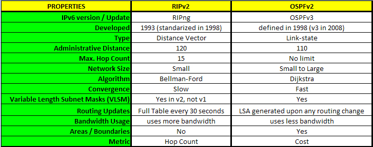
As you can see, OSPF looks to be the more beneficial routing protocol of the two to use. In a later article, I will discuss the similarities and differences between OSPFv2 and EIGRP (Enhanced Interior Gateway Routing Protocol) and from there, we can determine which of the two, under your network's circumstances, would be the most beneficial routing protocol to use for your network.
Monday, June 22, 2009
Configuring NAT Part 2: Static Translation
This article is a continuation of Part 1, so if you haven't read the part 1, I highly recommend that you go back and read Part 1. In this article, I will be assuming that you know how to configure the basic dynamic NAT configuration. However, if you are familiar with NAT and just want to read up on configuring a Static NAT, you can continue on without reverting to the previous NAT blog.
 Step 1: Determine inside and outside networks. Label each interface as “inside” or “outside” using the ip nat inside and ip nat outside commands at the interface or subinterface configuration mode.
Let's do a concise review of Dynamic NAT configuration before moving on.
Step 1: Determine inside and outside networks.- GatewayRouter(config)#int s0/0
GatewayRouter(config-if)#ip nat outside
GatewayRouter(config-if)#int fa1/0
GatewayRouter(config-if)#ip nat inside
Step 2: Ensure that the connectivity exists between the routers.
- GatewayRouter(config)#ip route 0.0.0.0 0.0.0.0 s0/0
Step 3: Configure a pool private IP addresses.
- GatewayRouter(config)#access-list 1 permit 10.0.0.0 0.0.0.255
Step 4: Configure a pool public IP addresses.
- GatewayRouter(config)#ip nat pool OUTSIDE 216.116.120.250 216.116.120.254 net 255.255.255.248
- GatewayRouter(config)#ip nat inside source list 1 pool OUTSIDE
----------------------------------------------------------------------------------------
What is Static NAT
A type of Network Address Translation where an one-to-one map exists between a public IP address and an internal, private IP address. This method is manual and static; as a result, it is more time consuming and does not automatically react to changes in networks.
So, what is its purpose? When you publish your webservers or Front-end Exchange servers, you will need to associate those servers with a public IP address so that the clients and users can access the servers from external networks. Likewise, the above servers will also require a private IP address for internal users to access them. Instead of using two NIC's to resolve the above issue, it's recommended to use Static NAT to more securely kill two birds with one stone. Here are the general steps when configuring a Static NAT:- Step 1: Determine inside and outside networks. Label each interface as “inside” or “outside” using the ip nat inside and ip nat outside commands at the interface or subinterface configuration mode.
- Step 2: Ensure that the connectivity exists between the routers. By using either static routes or dynamic routing protocols, make sure that your inside global network can connect to the outside network.
- Step 3: Configure Static Network Address Translation. Define components that will be translated.
- Step 4: Verify your work
In the below network diagram, let's configure a static NAT for the front-end Exchange Server.
 Step 1: Determine inside and outside networks. Label each interface as “inside” or “outside” using the ip nat inside and ip nat outside commands at the interface or subinterface configuration mode.
GatewayRouter#conf t
GatewayRouter(config)#int s0/0
GatewayRouter(config-if)#ip nat outside
GatewayRouter(config-if)#int fa1/0
GatewayRouter(config-if)#ip nat inside
Step 2: Ensure that the connectivity exists between the routers. By using either static routes or dynamic routing protocols, make sure that your inside global network can connect to the outside network.
GatewayRouter(config)#ip route 0.0.0.0 0.0.0.0 s0/0
Step 3: Configure Network Address Translation. Define components that will be translated.
GatewayRouter(config)#ip nat inside source static 10.1.0.25 216.116.120.252Note that for Static NAT, you do not need to configure a pool or an access-list.
Subscribe to:
Posts (Atom)