VTP (Vlan Trunking Protocol) modes are different ways a switch can be set to share or interact with VTP advertisements. The three modes are Server, client and Transparent.
Server mode is the default setting for Cisco catalyst switches. Within any VTP domain, there must contain at least one switch configured in server mode. When in this mode, the switch can be used to add, modify or delete VLAN related infrormation. These changes are then advertised to other switches in the same domain that are configured as either servers or clients. The receiving switches then compare the revision number from the received update and if the revision number is higher, then it changes its configuration
Client mode is simply a receiver of VTP information configured from a server. when in client mode, no changes can be mad to the switch.
Transparent mode is where a switch will not listen to VTP information being advertised but will pass on the information to other switches. It acts as a standalone device and any VLAN information can be configured.
Configuring the modes:
First we get into the vlan database.
SWITCH#vlan database
We can then type in the vtp command followed by a question mark to see the different options.
SWITCH(vlan)#vtp ?
client Set the device to client mode.
domain Set the name of the VTP administrative domain.
password Set the password for the VTP administrative domain.
pruning Set the administrative domain to permit pruning.
server Set the device to server mode.
transparent Set the device to transparent mode.
v2-mode Set the administrative domain to V2 mode.
for now we shall only concentrate on the three vtp mode options: Server, client and transparent.
To configure as a Server simply type in the vtp server command and you get a notification that the device is switching into server mode.
SWITCH(vlan)#vtp server
Setting device to VTP SERVER mode.
The same goes for configuring as a vtp client.
SWITCH(vlan)#vtp client
Setting device to VTP CLIENT mode.
as well as transparent mode.
SWITCH(vlan)#vtp transparent
Setting device to VTP TRANSPARENT mode
To save and exit into the vlan database, simply type in "exit".
SWITCH(vlan)#exit
APPLY completed.
Exiting....
To verify the VTP mode configured, we can use the "show vtp status" command.
SWITCH#sh vtp status
VTP Version : 2
Configuration Revision : 0
Maximum VLANs supported locally : 256
Number of existing VLANs : 7
VTP Operating Mode : Transparent
VTP Domain Name :
VTP Pruning Mode : Disabled
VTP V2 Mode : Disabled
VTP Traps Generation : Disabled
MD5 digest : 0x1A 0x47 0x70 0xB8 0xD1 0x2F 0x7E 0x32
Configuration last modified by 10.1.35.2 at 3-1-02 00:48:56
In this instance, the switch is in Transparent VTP operating mode.
Monday, June 29, 2009
Tuesday, June 23, 2009
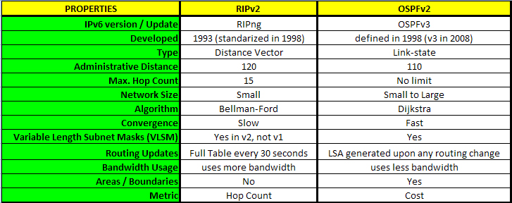
Part 1: Which Routing Protocol Should I Choose? RIPv2 vs. OSPF
When designing a network, one of the most important decisions you have to make is determining which routing protocol is best suited for the design of the network that you have created. I thought in this article I would create a simple table with some basic information in regards to some differences and similarities between two of the more popular, widely used routing protocols out there: RIPv2 (Routing Information Protocol) and OSPF (Open Shortest Path First). Below are some of the more important aspects of each routing protocol and hopefully they will aid you in choosing which protocol best suites the design of your network.

As you can see, OSPF looks to be the more beneficial routing protocol of the two to use. In a later article, I will discuss the similarities and differences between OSPFv2 and EIGRP (Enhanced Interior Gateway Routing Protocol) and from there, we can determine which of the two, under your network's circumstances, would be the most beneficial routing protocol to use for your network.
Monday, June 22, 2009
Configuring NAT Part 2: Static Translation
This article is a continuation of Part 1, so if you haven't read the part 1, I highly recommend that you go back and read Part 1. In this article, I will be assuming that you know how to configure the basic dynamic NAT configuration. However, if you are familiar with NAT and just want to read up on configuring a Static NAT, you can continue on without reverting to the previous NAT blog.
 Step 1: Determine inside and outside networks. Label each interface as “inside” or “outside” using the ip nat inside and ip nat outside commands at the interface or subinterface configuration mode.
Let's do a concise review of Dynamic NAT configuration before moving on.
Step 1: Determine inside and outside networks.- GatewayRouter(config)#int s0/0
GatewayRouter(config-if)#ip nat outside
GatewayRouter(config-if)#int fa1/0
GatewayRouter(config-if)#ip nat inside
Step 2: Ensure that the connectivity exists between the routers.
- GatewayRouter(config)#ip route 0.0.0.0 0.0.0.0 s0/0
Step 3: Configure a pool private IP addresses.
- GatewayRouter(config)#access-list 1 permit 10.0.0.0 0.0.0.255
Step 4: Configure a pool public IP addresses.
- GatewayRouter(config)#ip nat pool OUTSIDE 216.116.120.250 216.116.120.254 net 255.255.255.248
- GatewayRouter(config)#ip nat inside source list 1 pool OUTSIDE
----------------------------------------------------------------------------------------
What is Static NAT
A type of Network Address Translation where an one-to-one map exists between a public IP address and an internal, private IP address. This method is manual and static; as a result, it is more time consuming and does not automatically react to changes in networks.
So, what is its purpose? When you publish your webservers or Front-end Exchange servers, you will need to associate those servers with a public IP address so that the clients and users can access the servers from external networks. Likewise, the above servers will also require a private IP address for internal users to access them. Instead of using two NIC's to resolve the above issue, it's recommended to use Static NAT to more securely kill two birds with one stone. Here are the general steps when configuring a Static NAT:- Step 1: Determine inside and outside networks. Label each interface as “inside” or “outside” using the ip nat inside and ip nat outside commands at the interface or subinterface configuration mode.
- Step 2: Ensure that the connectivity exists between the routers. By using either static routes or dynamic routing protocols, make sure that your inside global network can connect to the outside network.
- Step 3: Configure Static Network Address Translation. Define components that will be translated.
- Step 4: Verify your work
In the below network diagram, let's configure a static NAT for the front-end Exchange Server.
 Step 1: Determine inside and outside networks. Label each interface as “inside” or “outside” using the ip nat inside and ip nat outside commands at the interface or subinterface configuration mode.
GatewayRouter#conf t
GatewayRouter(config)#int s0/0
GatewayRouter(config-if)#ip nat outside
GatewayRouter(config-if)#int fa1/0
GatewayRouter(config-if)#ip nat inside
Step 2: Ensure that the connectivity exists between the routers. By using either static routes or dynamic routing protocols, make sure that your inside global network can connect to the outside network.
GatewayRouter(config)#ip route 0.0.0.0 0.0.0.0 s0/0
Step 3: Configure Network Address Translation. Define components that will be translated.
GatewayRouter(config)#ip nat inside source static 10.1.0.25 216.116.120.252Note that for Static NAT, you do not need to configure a pool or an access-list.
Thursday, June 18, 2009
Are you late? Synchronize cisco router with Network Time Protocol (NTP)

One of the first thing you do when you purchase your desktop, laptop, cell phone, your PDA, server or mp3 player etc. is to check the calendar, check the time and hour. Is that right? I hope it is. Why should we not do the same with Cisco router (or switch). It is very important especially if you are about to read log information and understand them, or if you have VoIP system, this setting will be displayed on all phones. Yes, including your boss.
In this post, I will show you how to:
- check your current router clock
- synchronize using ntp to one of the public NTP server
- verify updated router clock
Cisco Router 2621 with IOS Version 12.3(19) was used during setup.
First let's check what is your current router clock setting:
Router#show clock
*07:34:56.011 UTC Sat Mar 20 1993
As we can see not so current. Check the date of this post to compare.
Find NTP server that you can synchronize to (http://support.ntp.org/bin/view/Servers/StratumOneTimeServers).
Try to ping it.
Router#ping selected.ntp.server
Translating "selected.ntp.server"...domain server (1.2.3.4) [OK]
If it works, you are ready to establish NTP peer. Which means you will be a client and selected host an NTP server.
It can be done by:
Router(config)#clock timezone PST -8
Router(config)#ntp peer selected.ntp.server
Router(config)#ntp source fa0/1
First line will setup you time zone. The second one is specifying source that will be used to synchronize your router time. In the last line, as you can see, we have specified a port in order to make sure that source IP is our public IP so NTP server can reach us.
At this point we would like to verify our work, by:
Router#show clock
17:18:57.505 PDT Thu Jun 18 2009
Great job!
I hope in your case it worked too. If not please check : http://www.cisco.com/en/US/docs/ios/12_1/configfun/configuration/guide/fcd303.html#wp1001612
or just go to:
http://www.cisco.com/univercd/home/home.htm
to find specific information about your particular model of device.
Wednesday, June 10, 2009
How to secure remote access to the cisco router (replace telnet with ssh)

This post essentially was going to be about how to enable ssh on the cisco router. But.. I realized that in many cases when I say to someone:
- You should stop using telnet while accessing your cisco device via public network (internet), because traffic is not encrypted and it is easy to sniff and see your passwords, your running config and anything you type and your router response. It is like having keylogger on your system. Use ssh instead, so traffic is encrypted and you are much safer.
That "someone" (you?) often says:
- Really? Oh.. probably it is not so easy to sniff, come on!
Because of this I will show how "safe" you are using telnet. The second reason is because I can see the analogy from martial arts (I hope you like it). Before you learn how to block/protect yourself, you need to know how to strike first!
Please take a look at Figure 1. We will telnet from Microsoft Windows "XP" to Router "R", sniff the telnet traffi using wireshark, decode and read.
Below are scary results:


No way! You might say. As you can see if you use telnet someone can learn your passwords and your config, and if someone has bad day that time may wipe out your router config and reboot... You probably do not want to come to work and see this in the morning do you?
Let's fix it and enable ssh:
en
conf t
username cisco password cisco
aaa new-model
ip domain-name mydomain.com
cry key generate rsa
!
! --- use 2048 bit as a key length, and allow couple minutes for your router to generate key
!
line vty 0 4
!--- enable ssh service only
transport input ssh
end
wr
It will look like:

We are done, now we should use ssh client, from windows we will use putty. Take a look what can we sniff this time:


Try to guess my password now!
As we can see the security level has been improved a lot. It did not take too much effort either. I hope it will help to understand that telnet should be replaced by ssh usage, unless you do no care about security of your passwords or running config. It is possible if you are just using the router for quick and dirty testing or learning purposes.
Note: Please note that after you changed your connection type from telnet to ssh, you should change all passwords since someone could already sniff the current one.
Make sure your IOS support ssh using Ciso IOS advisor:
http://tools.cisco.com/ITDIT/ISTMAIN/servlet/index
(IOS used in this post was 12.4(9)T1 with Cisco 3745 router.)
More info:
http://www.cisco.com/en/US/tech/tk583/tk617/technologies_tech_note09186a00800949e2.shtml
Friday, June 5, 2009
Whats the purpose of Cisco-Loopback ip addresses?
What is a purpose of a cisco loopback address? It is not assigned to any physical ports and cannot connect any networks to it. It almost seems useless and a waste of precious IP addresses. Furthermore, how do I go about assigning one.
Most people with a background in working with desktop computers have come across a loopback address, the most common being 127.0.0.1 that loops you back to your machine and checks pinging it checks if your TCP/IP stack is up and running.
With cisco devices, loopback addresses are virtual and are not assigned to physical interfaces that you can see. It can be a very powerful tool in any infrastructure as its strongest characteristic is that it never goes down unless the whole device goes down. This is very significant to processes that use IP addresses to point to a particular device. One example is ospf that uses router id's to establish neighbor addresses. The router ID is determined as the highest active loopback address. If this is not available then the highest IP address is chosen. In a situation where a physical port goes down that happens to be the root-id then the router is deemed to be unavailable, resulting in a whole election process for all routes through that router, even though in reality the other routes are still available. Another example of the use of loopback addresses is in lab environments to simulate networks behind a router. Assignig a loopback address is a simple task as shown below:
Router(config)#interface loopback 1
Router(config-if)#ip address 192.168.0.1 255.255.255.0
Router(config-if)#exit
Where the the number "1" is the loopback interface number and is locally significant. The address can be verified on the running config as well as usinig the "show ip interface brief command"
Serial0/0 unassigned YES unset administratively down down
Serial0/1 unassigned YES unset administratively down down
Serial0/2 unassigned YES unset administratively down down
Serial0/3 unassigned YES unset administratively down down
FastEthernet1/0 unassigned YES unset administratively down down
Loopback1 192.168.0.1 YES manual up up
As we can see, the interface immediately shows up as up and up even when all the other interfaces are down. Loopback addresses are great for management and if utilized properly can be a great tool to ping and check if your routers are up and running as well as for remote connection to a device.
What other uses can you think of ?
Wednesday, June 3, 2009
Configuring NAT Part 1: Dynamic Translation
NAT was introduced to help resolve the issue of IP Address shortages. With a fast growing number of devices that require an IP Address, many experts predicted that the pool of IP addresses will run out soon. Before a well thought out, long-term solution can be implemented, a few short-term solutions were introduced. Amongst ingenious solutions such as CIDR and Private IP addresses, NAT was introduced.

Step 0: Configure base configuration and assign IP addresses according to above diagram
Router>enable
Router#configure terminal
Router(config)#hostname GatewayRouter
GatewayRouter(config)#interface s0/0
GatewayRouter(config-if)#ip add 216.116.120.250 255.255.255.248
GatewayRouter(config-if)#no shutdown
GatewayRouter(config-if)#int fa1/0
GatewayRouter(config-if)#ip add 10.0.0.1 255.255.255.0
GatewayRouter(config-if)#no shut
Step 5: Configure Network Address Translation. Define components that will be translated.

The term NAT is used by many vendors, and it may differ slightly depending on which equipment you are using to configure NAT. In this blog, we will be exploring NAT used by Cisco IOS.
Here are general steps when configuring a NAT:- Step 1: Determine inside and outside networks. Label each interface as “inside” or “outside” using the ip nat inside and ip nat outside commands at the interface or subinterface configuration mode.
- Step 2: Ensure that the connectivity exists between the routers. By using either static routes or dynamic routing protocols, make sure that your inside global network can connect to the outside network.
- Step 3: Configure a pool private IP addresses that will be allowed to access the external network
- Step 4: Configure a pool public IP addresses that will be used by your internal network to access the external network
- Step 5: Configure Network Address Translation. Define components that will be translated.
- Step 6: Verify your work
Let's configure the Gateway Router from the below diagram so that the PC's in the internal network can communicate with the devices in external networks.

Step 0: Configure base configuration and assign IP addresses according to above diagram
Router>enable
Router#configure terminal
Router(config)#hostname GatewayRouter
GatewayRouter(config)#interface s0/0
GatewayRouter(config-if)#ip add 216.116.120.250 255.255.255.248
GatewayRouter(config-if)#no shutdown
GatewayRouter(config-if)#int fa1/0
GatewayRouter(config-if)#ip add 10.0.0.1 255.255.255.0
GatewayRouter(config-if)#no shut
Always verify that IP addresses are inputted properly and the Status and Protocol are both up.
-------------------------------------------------------
Step 1: Determine inside and outside networks. Label each interface as “inside” or “outside” using the ip nat inside and ip nat outside commands at the interface or subinterface configuration mode.GatewayRouter#conf t
GatewayRouter(config)#int s0/0
GatewayRouter(config-if)#ip nat outside
GatewayRouter(config-if)#int fa1/0
GatewayRouter(config-if)#ip nat inside
-------------------------------------------------------
GatewayRouter(config)#ip route 0.0.0.0 0.0.0.0 s0/0
-------------------------------------------------------
You need to specify the source addresses that will be translated. In this exercise, you will be using an access-list to specify a pool of IP addresses. We will be allowing all internal IP addresses to pass through the gateway router.
GatewayRouter(config)#access-list 1 permit 10.0.0.0 0.0.0.255
-------------------------------------------------------
Next step is to specify the pool of IP addresses that will be used as Inside Global IP Addresses. Ensure that the pool name specified in the previous command matches the pool name you will be creating in the below command line. Please note that pool name is case-sensitive.
GatewayRouter(config)#ip nat pool OUTSIDE 216.116.120.250 216.116.120.254 net 255.255.255.248
Note that the first IP address marks the starting point of the Inside Global IP Address and the second IP address marks the last Inside Global IP Address to be used for NAT.
-------------------------------------------------------Step 5: Configure Network Address Translation. Define components that will be translated.
GatewayRouter(config)#ip nat inside source list 1 pool OUTSIDE
As you can see there are many options to choose from. Let’s go over the options that we chose.
-------------------------------------------------------
Step 6: VerificationThe last step is to verify that the Network Address Translation works. You can login to one of your PCs and ping out to the internet. If you have a DNS set up, you can ping a known websites such as google.com or yahoo.com. If your internet network does not have a DNS setup, try to ping an external DNS such as 4.2.2.3. Once you have successfully pinged an external entity, you can revert to GatewayRouter to verify the translation.

Translation is successful. Please note that port number from the output will vary, but the port numbers from Inside global and Inside local will generally match.
Subscribe to:
Posts (Atom)